Instrument Approach Procedures
Approach procedure charts (commonly referred to as "approach plates") are published every 56 days (8 weeks) in the US Terminal Procedures Publications (TPP). There are currently 24 different TPP booklets for the continental United States. More commonly now, they are downloaded on EFB applications like ForeFlight, Garmin Pilot, FltPlan Go, etc.
An approach chart is broken into four primary sections:
- Margin identification
- Plan View
- Profile View
- Airport environment
Margin Identification
The margin identification section is the header at top and bottom of the chart. It depicts the airport location and procedure identification, among other information.
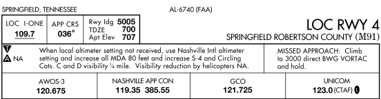
You will first note some information printed at the top over the margin ID. The charts are listed in order of city and state in the TPP book, so you will find the city and state at the top left over the margin ID section.
The number at the top center over the margin is the FAA chart reference number.
Finally, the top right contains the approach type and runway number (if any). A runway number is listed when the approach course is aligned within 30° of the runway centerline to straight-in landing. If it is more than 30° from the centerline, a letter is assigned instead: "VOR-A".
The top row of the boxes in the margin ID contains (in this case): the localizer frequency, the final approach course, and the runway landing length (5005 ft), touchdown zone elevation (700 msl), and the airport elevation (707 msl).
The middle row has two boxes: a notes box, and a box for information on the missed approach. You'll note a bolded "T" and "A" in the notes section. The "T" signifies that the airport has non-standard IFR takeoff minimums. This applies to 121 and 135 operators, as there are no regulatory IFR takeoff minimums for Part 91 operations.
The bolded "A" signifies that non-standard alternate minimums exist for the airport (the usual alternate minimums being 600-1 and 800-1. If "NA" is specified it indicates that alternate minimums are not authorized due to it being an unmonitored facility or lack of a weather reporting service. This means you cannot use that approach to determine, during preflight planning, if you can choose this airport as an alternate. If all the approaches at that airport specify "NA", you may not use the airport as an alternate.
The missed approach section will give you a textual description of the missed approach procedure and should be reviewed carefully each time you brief the approach.
The bottom row in the margin identification section has the important frequencies for the airport. These include the weather, approach/departure, unicom, tower, ground, etc frequencies.
Plan View
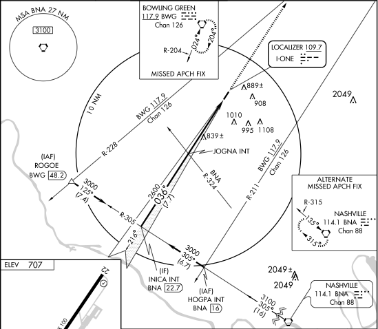
The Plan View provides a graphical, overhead view of the approach procedure. The majority of NACO charts contain a reference or distance circle with a 10nm radius. Only the data within this reference circle is drawn to scale. When a route segment outside the circle is drawn to scale, the symbol is two jagged lines and it interrupts the segment. Dashed circles or concentric rings around the distance circle are used when information necessary to the procedure will not fit to scale within the limits of the plan view area.
The final approach course is the thick, solid line. You'll note it agrees with the course specified in the margin box at the top. A DME arc is also think line (see my DME arc page). A feeder route is medium thickness line and indicates a transition from the enroute structure to an initial approach fix. Radials are represented as thin lines.
Minimum Safe Altitude
The MSA (minimum safe altitude) circle appears in the plan view except in approaches for which the navaid is unavailable. The MSA circle guarantees 1000 ft clearance over obstacles and terrain.
The circle contains the facility ID of the navaid used to determine the MSA. For RNAV approaches, the MSA is based on the runway waypoint for straight-in approaches or the airport waypoint for circling approaches. For GPS approaches, the MSA center will be the missed approach waypoint. The altitudes appear in boxes within the circle.
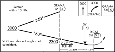
Procedure Turns
Procedure turns are a... well... turning procedure depicted on an approach chart that allow a pilot to lose altitude, choose from a larger number of initial approach fixes, and reverse course when necessary to complete a stablized approach.
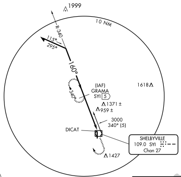
The barbed arrow indicates the direction of turn or side of outbound course on which turn is made. The absence of the procedure turn barb in the plan view, or the letters "NoPT", indicate that a procedure turn is not authorized for that procedure. The headings are provided on top/bottom of arrow. In this case , the pilot would fly to the GRAMA initial approach fix (IAF), then fly outbound on the 340 radial, then turn left to heading 295°, fly for 1 minute (approximately, depends on aircraft speed), then turn right 180° to heading 115°, and finally intercept the 160° approach course with a right turn. The pilot may also execute a teardrop, 80/260, or racetrack procedure turn, provided it is performed on the protected (barbed arrow) side of the approach course.
The point at which the turn may be commenced and the type and rate of turn is left to discretion of the pilot. Typically an outbound leg is between 1-2 minutes, and the pilot will turn at a standard rate. The pilot must adhere to a maximum procedure turn speed of not greater than 200 knots KIAS. Additionally, the procedure turn maneuver must be executed within the distance specified in the profile view. A normal procedure turn distance is 10nm, but this distance may be increased to as much as 15nm to accommodate high performance AC.
Terminal Arrival Area (TAA)
The terminal arrival area is another transition method for aircraft with GPS/RNAV equipment. They divide a terminal area into multiple segments with differing altitudes and initial approach fixes for aircraft approaching from the different segments. TAAs will also eliminate or reduce the need for feeder routes, departure extensions, and procedure turns or course reversals.
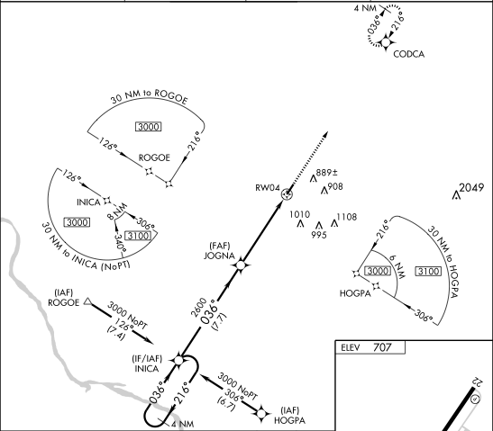
The idea is that an aircraft approach the airport environment from the southeast on a heading of 320° would use an MSA of 3100 feet and HOGPA as the initial approach fix. An aircraft approach from the southwest would use an MSA of 3000 feet and ROGOE as the initial approach fix.
It is worth noting that if a pilot flying at 5000 feet is cleared for this approach while 25nm southwest of ROGOE, the pilot is expected to descend to 3000 feet as depicted on the TAA as soon as practical.
Profile View
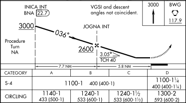
The profile view is a drawing of the side view of a procedure that illustrates the vertical approach path altitudes, headings, distances, and fixes. It includes the minimum altitudes and maximum distance for a procedure turn, altitudes over prescribed fixes, distances between fixes, and the missed approach procedure. Please note the profiles view is NOT drawn to scale.
In non-precision approaches, the final descent is initiated at the final approach fix (FAF), which is represented by a maltese cross on the chart. Step-down fixes in non-precision procedures are provided between the FAF and the airport for authorizing a lower MDA after passing an obstruction. They are represented by vertical dashed line.
Glide-slope intercept altitude is represented by lightning symbol.
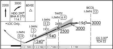
Minimums and Notes
The altitude minimums for the approach are located at the bottom of the profile section.
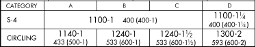
The minimums are separated by approach "category", which is determined by the speed of the aircraft flying the approach.
| Category | Speed |
|---|---|
| A | 0-90 |
| B | 91-120 |
| C | 121-140 |
| D | 141-165 |
| E | 166+ |
If it is necessary to maneuver at speeds in excess of the upper limit of a speed range for a category, the minimums for the next higher category should be used. Always use the category which includes the fastest speed utilized throughout the approach.
Minimums are typically specified by altitude followed by visibility requirements. For example, 530-1 indicates "530 MSL" and "1 sm visibility". A RVR (runway visual range) value is separated from minimum altitude with a slash, such as "1065/24" which indicates 1,065 MSL and an RVR of 2,400 ft. On NACO charts, figures listed parenthetically are for military ops.
When a fix is incorporated in a non-prescision final segment, two sets of minimums may be published, depending upon whether or not fix can be identified.
Precision approraches use a decision altitude (DA) charted in MSL followed by decision height (DH) referenced in height above threshold elevation (HAT). Non-precision approaches use a minimum descent altitude (MDA). The primary difference being that when a pilot reaches a DA, the missed approach must immediately be executed if the runway environment is not yet in sight. With an MDA, the pilot levels off at or above that altitude and continues until either the missed approach point, or the runway environment comes into view.
Visual Descent Point
A visual descent point (VDP) is identified on the profile view of an approach chart by "V" symbol.
VDPs are being incorporated in non-precision approach procedures by the FAA. A VDP is a defined point on the final course of a non-precision, straight-in approach procedure from which a normal descent from the MDA to the runway touchdown point may be commenced, provided visual reference required by 91.175 is established.
Airport Environment
Finally, in the lower right of the NACO approach chart you will fine the airport information section.
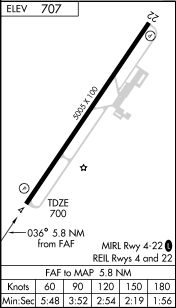
At the top left, you'll see the airport elevation. In the middle is, obviously, the runway environment, lighting facilities, runway lengths, etc.
Just below that, on most non-GPS approaches, you will find the section on time to the missed approach point (FAF to MAP). The first row indicates the groundspeed at which the airplane is approach the MAP. The second row tells how long to time between the FAF and the MAP at the speed given above before beginning a missed approach.
For example, in this approach, you would begin timing at the final approach fix (FAF). If you are hurling towards the MAP at 120 knots, then you would begin the missed approach when the clock reaches 2 minutes and 54 seconds. At 90 knots, you would go missed at 3 minutes 52 seconds. At 105 knots, you would interpolate between the two and executed the missed at 3 minutes 21 seconds.
Briefing the Approach
Remember SCAMR. Like a Nigerian scammer, but with worse spelling:
S - Source. What is the navigational source for the approach? Tune it, ID it, and check the CDI.
C - Course. Set the inbound approach course on your HSI or OBS.
A - Altitude. What are the minimums for the approach? Either the decision altitude or the MDA. Memorize it.
M - Missed. Brief the missed approach procedure. Also, determine where you should begin the missed approach.
R - Radios. Set and listen to the weather and CTAF or tower frequencies for the airport.