Beechcraft Baron BE55
Powerplants
- Two Continental IO-470-L, six-cylinder, horizontally-opposed, fuel-injected engines, each rated at 260 HP at 2625 RPM
- Conventional full pressure, wet sump system
- Oil - Aeroshell 15W-50. Min operating quantity 9 quarts, max capacity 12 quarts
Propellers
- Hartzell 2-blade constant speed. Pitch range: 16° at low pitch to 80° at fully feathered
- Diameter: 76.5 – 78 inches
- Pitch stops determine governing range
- No unfeathering accumulators.
- No synchronizer or synchrophaser.
Speeds
- Vr - 84 kts
- Vy - 107 kts
- Vx - 84 kts
- Va - 157 kts
- Vfe - 153 kts approach / 122 kts full flaps
- Vle - 153 kts
- Vsse - 84 kts
- Vyse - 100 kts
- Vxse - 91 kts
- Vmc - 78 kts
- Vg - 120 kts
- Vs0 - 68 kts
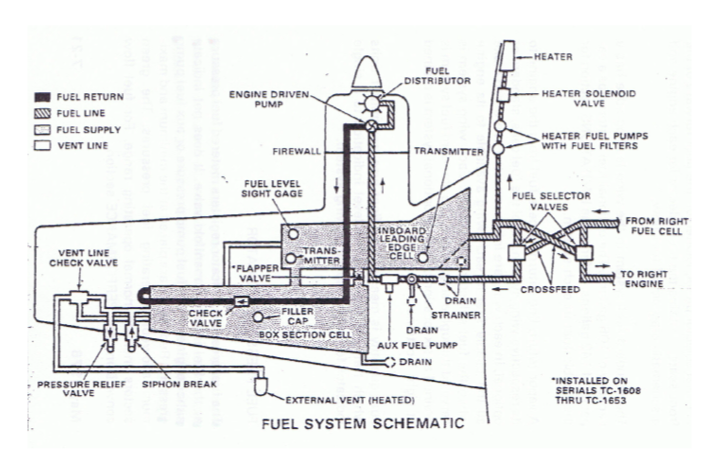
Fuel System
- Simple ON-OFF-CROSSFEED arrangement – Crossfeed used only during single-engine operation.
- Fuel system capacity - 142 gallons, 136 useable 100LL. Fuel level sight gauge (40 – 65 gal/side). Each wing tank system serviced by single filler
- 4 drains on each side (3 in front, 1 in back under flap).
- Fuel pumps – 2 engine driven pumps and 2 aux pumps
Auxiliary Fuel Pumps
- HI pressure used before start and for engine- driven fuel pump failure
- LO pressure used for high ambient temperatures to reduce pressure fluctuations. Use on takeoff only above 90°
Engine Indicators
- Tachometer (RPM) (Tach-generator)
- Manifold Absolute Pressure (MAP) – Before start indicates ambient pressure
- CHT and Oil Temp – Electrically-powered transducers
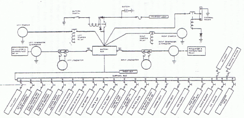
Electrical System
- Battery – One 17 ampere-hour, 24V battery – Located beneath floor of nose baggage compartment
- Alternators - Two 50A, 24V belt-driven alternators. Controlled by two voltage regulators selectable by switch below pilot subpanel. Output indicated by loadmeters, should be less than .2 after two minutes at 1000 – 1200 RPM after start
- ALTERNATOR warning lights indicate failure
External Power
Located on outboard side of left engine nacelle. Power unit should be capable of delivering 300A. Turn electrical systems OFF prior to connecting external power unit Once connected, turn BAT switch ON.
Total electrical load of twin-engine airplanes usually limited to 80% of combined output. Includes paralleling features that distribute electrical system demands between power sources. If only one generating system is operating, the electrical load may exceed the output rating of the remaining alternator, so the pilot must monitor the electrical system.
Cooling and Exhaust
- Air-cooled engines
- Cowl flaps manually controlled by lever located on lower center console. Closed when lever is in UP position, open when lever is DOWN. Generally, cowl flaps are OPEN for ground operations or climbs, and progressively CLOSED for cruise and descent
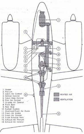
Cabin Environmental System
- Combustion heater located in nose cone.
- Heat-actuated CB located on heater
- 3-position switch: BLOWER – OFF – HEATER
- Blower automatically shuts off when landing gear is retracted or CABIN AIR T-Handle is pulled approximately halfway out
- CABIN AIR T-Handle regulates intake air - push control full forward for max intake air volume
- CABIN HEAT control regulates temperature of heated air - pull control to increase temperature of heated air
- DEFROST – Push for windshield defrosting.
- PILOT AIR – Pull out to direct heated air to pilot’s feet.
- COPILOT AIR – Directs air to co-pilot’s feet and right rear passenger seat.
- To provide unheated air to same cabin outlets as heated air, push CABIN AIR and CABIN HEAT controls full forward
- Individual Fresh Air Outlets – Master control in overhead panel – Volume of air regulated at each outlet
Weight and Balance
- Basic empty weight (3426 lbs)
- Useful Load (1674 lbs, 858 lbs with full fuel)
- Max ramp weight (5121 lbs)
- Maximum take-off weight (5100 lbs)
- Maximum landing weight (5100 lbs)
- No zero-fuel weight
Deice Systems
This is a deiced Baron, but is not certified for Flight Into Known Icing (FIKI). Here is a brief description of the deice systems:
Surface de-ice system
- Leading edges of wings and tail surfaces
- 3-position spring-loaded switch
- AUTO (up) – Boots inflate for 5-6 seconds then deflate
- OFF (center)
- MAN (down) – Boots inflate for as long as switch is operated
- Wing ice lights
Propeller anti-ice system
- Pump delivers anti-icing fluid (alcohol) to anti-ice boots that direct fluid along propeller blades
- Pump controlled by ON-OFF switch
Misc
- PITOT HEAT LT and RT switches
- Stall warning anti-ice - Activated when PITOT HEAT LT switch is on
- Heated fuel vents controlled by FUEL VENT switch
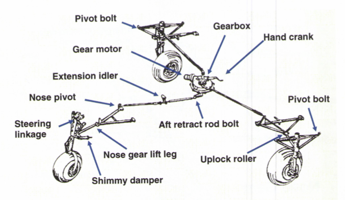
Landing Gear
Adjustable linkage connected to an actuator assembly located under front seats. Actuator driven by an electric motor. The landing gear may be electrically retracted and extended, and may be extended manually.
- Control switch is a 2-position switch on right side of center console
- Gear position lights – 3 green lights, one red in-transit light – Dimmed when nav lights are turned on
- Gear warning horn – Either or both throttles retarded to below approx 13” MAP
- Main strut safety switch to prevent gear retraction on the ground.
Bear in mind that newer Barons (built after 1983) have switched positions for the flap and landing gear switches, leading to confusion for pilots that fly both newer and older models. The landing gear switch looks and feels like a wheel, and the flap looks and feels like a flap.
To prevent accidental retraction on the ground I recommend one of the following after pulling off the runway and stopping the airplane:
- Grab the flap handle and say "This is the flaps and not the gear", visually verify that fact, and then raise the flaps - OR -
- Grab the flap handle and say "Looks like a flap, feels like a flap", visually verify you have the flaps, and raise them
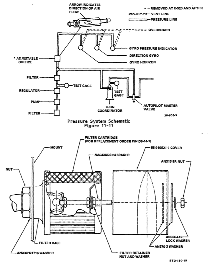
Pneumatic System
Powers both flight instruments and deice boots.
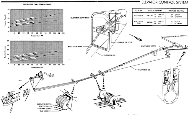
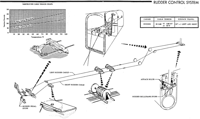
Control Surfaces
Hydraulic System
- Only hydraulic system on the Baron controls the brakes. Brakes installed only on pilot’s side.
- Parking brake T-handle located just left of elevator trim wheel. Pull handle and depress brakes until firm.
- Hydraulic fluid reservoir accessible through nose baggage door. Dipstick attached to reservoir cap.
Preflight
There are a few things specific to the Beechcraft line that should be checked on preflight inspection.
- Gear uplock springs
- Gear uplock rollers
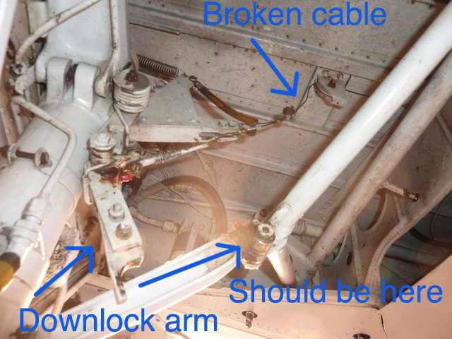
- Gear downlock lever and cable
- Emergency gear extension handle (locked behind pilot/copilot seats)
- Locking nuts securing connecting rods to elevator trim tabs should turn freely
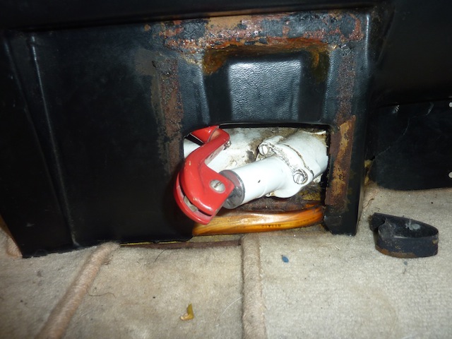
Here are a couple of them that were recently found NOT to be in proper order. The first is the downlock lever. The cable had broken leaving the lever hanging down as pictured here. Normally it should be up and the cut out portion of it should rest against the silver uplock roller.
Here is a picture of the emergency gear handle which is covered (trapped) by the forward spar cover. Should you have a gear extension failure and the handle is trapped like this, there is no way to manually extend the gear. Always check that the handle can be engaged as part of your preflight cockpit checks.